Axial Flux Motors
1. Fundamental Magnetic Flux Orientation
graph LR
    subgraph "Radial Flux Motor"
        A[Stator] --> B[Air Gap]
        B --> C[Rotor]
        D[Flux Direction: ⟂ to shaft]
    end

    subgraph "Axial Flux Motor"
        E[Stator Disc] --> F[Air Gap]
        F --> G[Rotor Disc]
        H[Flux Direction: ∥ to shaft]
    end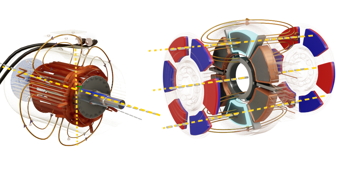
Radial Flux Motors (Traditional)
- Flux Direction: Magnetic flux flows radially from rotor to stator (perpendicular to shaft axis)
- Air Gap: Cylindrical air gap between rotor and stator
- Magnetic Circuit: Flux crosses the air gap in the radial direction
- Field Distribution: Magnetic field lines are perpendicular to the axis of rotation
Axial Flux Motors
- Flux Direction: Magnetic flux flows axially along the shaft direction (parallel to shaft axis)
- Air Gap: Flat, disc-shaped air gap(s) parallel to rotor face
- Magnetic Circuit: Flux crosses the air gap in the axial direction
- Field Distribution: Magnetic field lines are parallel to the axis of rotation
2. Construction Architecture
graph TD
    subgraph "Radial Flux Construction"
        A1[Cylindrical Stator] --> A2[Slotted Core]
        A2 --> A3[Distributed Windings]
        A4[Inner Rotor] --> A5[Magnets/Windings]
        A5 --> A6[Cylindrical Air Gap]
    end
graph TD
subgraph "Axial Flux Construction"
B1[Disc Stator] --> B2[Concentrated Windings]
B3[Disc Rotor] --> B4[Surface Magnets]
B4 --> B5[Flat Air Gap]
B6[L/D Ratio less than 0.3]
endRadial Flux Design
Traditional cylindrical construction:
- Stator: Cylindrical with slots for windings
- Rotor: Inner cylinder with magnets/windings
- Length/Diameter Ratio: Typically
- Cooling: Radial heat dissipation paths
Axial Flux Design
Disc-like construction:
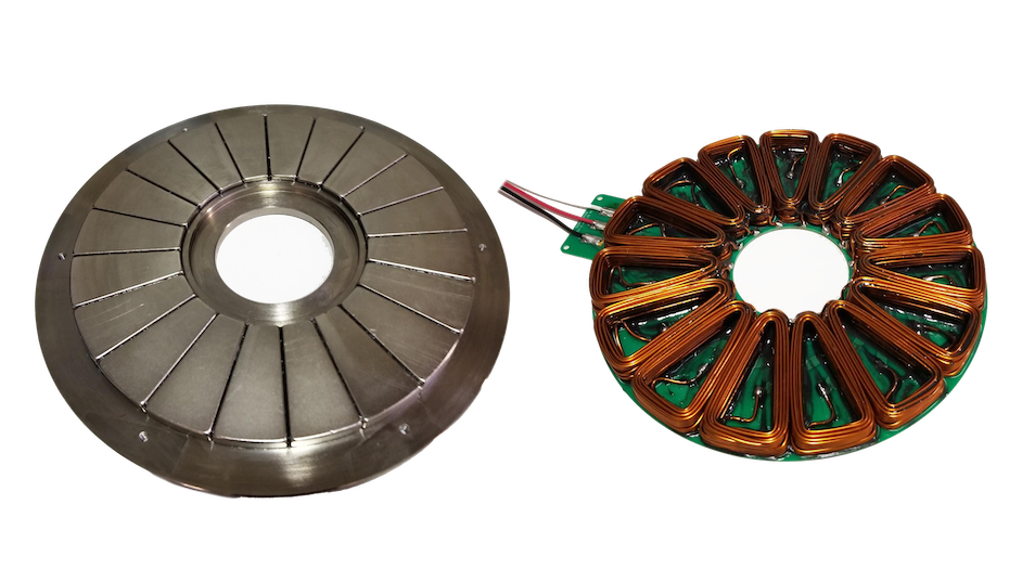
- Stator: Flat disc with concentrated windings
- Rotor: Disc with surface-mounted magnets
- Length/Diameter Ratio: Very low
- Cooling: Axial heat dissipation through large surfaces
3. Electromagnetic Theory Differences
graph LR
    subgraph "Torque Generation"
        A[Magnetic Field B] --> C[Force on Conductor]
        B[Current I] --> C
        C --> D[Torque = r × F]
    end

    subgraph "Scaling Laws"
        E[Radial: T ∝ D²L]
        F[Axial: T ∝ D³]
    end
Torque Production
Radial Flux:
- Active length is axial dimension
- Torque density limited by radial magnetic loading
Axial Flux:
- Active area scales with radius squared
- Higher torque density potential at larger diameters
EMF Generation
Radial Flux:
where
- Flux linkage through cylindrical surface
Axial Flux:
where
- Flux linkage through disc surface
- Higher EMF at larger radii due to increased velocity:
4. Magnetic Circuit Analysis
graph TD
    subgraph "Radial Flux Path"
        A1[N Pole] --> A2[Air Gap]
        A2 --> A3[Stator Tooth]
        A3 --> A4[Stator Back Iron]
        A4 --> A5[Return Path]
        A5 --> A6[S Pole]
    end

    subgraph "Axial Flux Path"
        B1[N Pole] --> B2[Axial Air Gap]
        B2 --> B3[Stator Core]
        B3 --> B4[Radial Return]
        B4 --> B5[S Pole]
    end
Reluctance Considerations
Radial Flux:
where
- Magnetic path through cylindrical iron core
- Flux density uniform across air gap height
Axial Flux:
where
- Magnetic path through disc-shaped iron core
- Variable reluctance with radius
- Non-uniform flux density (higher at inner radius)
Leakage Flux
Radial Flux:
- End-turn leakage at motor ends
- Slot leakage between conductors
- Predictable leakage patterns
Axial Flux:
- Edge effects at disc periphery
- Inter-disc leakage in double-sided designs
- 3D magnetic field effects more significant
5. Power Density & Scaling Laws
graph LR
    subgraph "Scaling Relationships"
        A[Radial: P ∝ D²L] --> C[Linear Volume]
        B[Axial: P ∝ D³] --> D[Cubic Diameter]
        end
graph TD
subgraph "Heat & Surface Area"
E[Heat ∝ Surface Area] --> F[Radial: ∝ DL]
E --> G[Axial: ∝ D²]
endRadial Flux Scaling
where
- Limited by aspect ratio constraints
- Heat dissipation through cylindrical surface
Axial Flux Scaling
- Superior scaling for larger diameters
- Heat dissipation through flat surfaces
- Better power-to-weight ratio for large diameters
Power Density Comparison:
where
6. Winding Configurations
flowchart TD
    A[Radial Windings] --> B[Long End Turns]
    C[Axial Windings] --> D[Short End Turns]
    B --> E[Higher Resistance]
    D --> F[Lower Resistance]
Radial Flux
- Distributed windings: Conductors spread across multiple slots
- Concentrated windings: Each coil around single tooth
- Resistance:
where includes long end turns - Standard 3-phase winding arrangements
Axial Flux
- Toroidal windings: Around disc core (less common)
- Concentrated non-overlapping: Each coil encircles single tooth
- PCB windings: Flat spiral conductors
- Resistance: Lower due to shorter end turns:
7. Performance Characteristics
graph TD
    A[Losses] --> B[Copper I²R]
    A --> C[Iron Core]
    A --> D[Mechanical]
graph LR
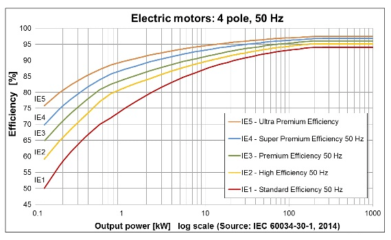
E[Efficiency] --> F[Pout/Pin]Efficiency Comparison
General Efficiency Formula:
Radial Flux:
- Mature technology with optimized designs
- Well-understood losses and mitigation
- Efficiency:
depending on size/design
Axial Flux:
- Potentially higher efficiency due to:
- Shorter end turns:
- Better heat dissipation:
- Optimized magnetic circuit
- Shorter end turns:
- Efficiency:
in well-designed systems
Speed Capabilities
Mechanical Speed Limit:
where
Radial Flux:
- Standard bearings and mounting
- Rotor dynamics well understood
Axial Flux:
- Lower rotational inertia:
(disc) vs (cylinder) - Axial magnetic forces:
- Potential for higher acceleration:
8. Design Trade-offs
graph LR
        A[Cost] --> A1[Radial: Lower]
        A --> A2[Axial: Higher]
graph LR
B[Power Density] --> B1[Radial: Good]
B --> B2[Axial: Excellent]graph LR
C[Manufacturing] --> C1[Radial: Mature]
C --> C2[Axial: Complex]graph LR
D[Cooling] --> D1[Radial: Limited]
D --> D2[Axial: Superior]Advantages & Disadvantages
| Aspect | Radial Flux | Axial Flux |
|---|---|---|
| Manufacturing | Mature, standardized | Complex, specialized tooling |
| Cost | Lower (volume production) | Higher (specialized) |
| Power Density | Good for small-medium sizes | Excellent for large diameters |
| Cooling | Limited surface area | Large flat surfaces |
| Bearing Loads | Radial forces only | Axial + radial forces |
| Scalability | Linear with volume | Cubic with diameter |
Cost Analysis:
9. Applications & Selection Criteria
flowchart TD
    A[Motor Selection] --> B{Application?}
    B -->|Standard| C[Radial]
    B -->|Space Limited| D[Axial]
    B -->|Cost Critical| C
    B -->|High Power| D
Choose Radial Flux When:
- Standard industrial applications
- Cost is primary concern:
- Proven reliability required
- Small to medium power ratings (
) - Established supply chains needed
Choose Axial Flux When:
- Space constraints (pancake form factor):
- High power density required:
- Direct drive applications:
- Wheel hub motors:
- Large diameter, low speed:
,
Selection Formula:
10. Future Developments
timeline
    title Motor Technology Evolution

    2020 : Traditional Radial Flux
         : Silicon Steel Cores
         : Ferrite Magnets

    2025 : Advanced Materials
         : Amorphous Steel
         : Rare Earth Magnets
         : Better Thermal Management

    2030 : Manufacturing Revolution
         : 3D Printed Components
         : Automated Winding
         : Cost Reduction

    2035 : Next Generation
         : AI-Optimized Designs
         : Novel Cooling Systems
         : Modular Architecture
Radial Flux Evolution
- Advanced materials (rare earth magnets, amorphous steel)
- Improved manufacturing techniques
- Better thermal management:
- Higher speed capabilities
Axial Flux Innovation
- Manufacturing cost reduction
- 3D printed components
- Advanced magnetic materials:
- Integrated thermal management
- Modular designs for scalability
Technology Readiness Levels:
PCB Motor Adaptation of Axial Flux Design
- PCB motors represent the ultimate evolution of axial flux motor technology, leveraging printed circuit board manufacturing to create ultra-flat, highly efficient motors.
- The inherent disc geometry of axial flux motors translates perfectly to PCB construction, where copper windings are etched directly onto flat substrates rather than wound with traditional wire.
Key Adaptations: - Flat spiral windings replace bulky 3D coils, eliminating end turns entirely
- Multi-layer PCB stacks create concentrated magnetic fields in minimal axial space
- Precise manufacturing tolerances from PCB fabrication enable tighter air gaps
- Integrated cooling through copper pours and thermal vias in the PCB substrate
References